
As mentioned in my Temp Buddy overview, I’m building a remote temperature sensing system to measure the differences in temperature between rooms in my house. In order to maximize system flexibility and scalability, each temperature sensor will be connected to my home network and serve temperature data through a simple API. In the future, this API can be extended to provide error data for system logging, readings from other sensors, etc.
Hardware
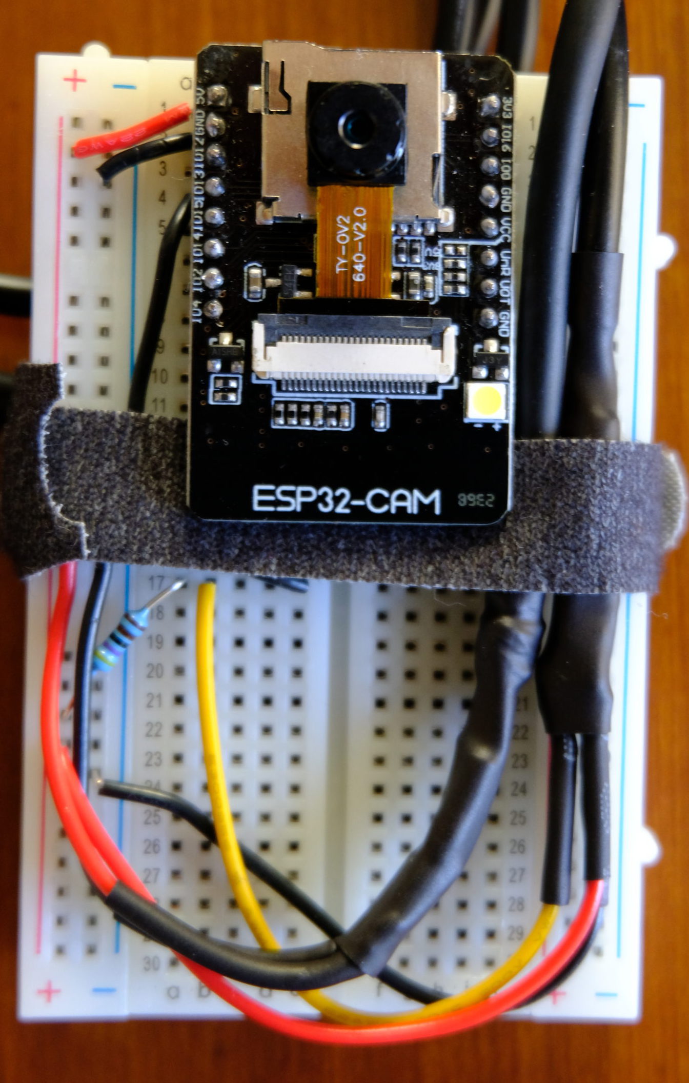
I chose to build my temperature sensors around the ESP32-CAM microcontroller. Why? I had three on hand from a previous project and they’re dirt cheap ($9 for a wifi/bluetooth microcontroller) if I wanted to expand my sensor net. They aren’t necessarily the best PSoCs for this project because they need power through pins rather than a convenient micro-USB socket. If I were to start over, I’d probably choose the ESP-WROOM-32 ($11) for its micro-USB power and more GPIO options. There are tons of other PSoCs out there but the ESP32 family nicely combines affordability with onboard wifi.
The temperature sensor is a waterproof DS18B20 digital thermal probe and costs about $2. You can pick up non-waterproof sensors for a quarter of the price but it’s worth the extra $1.50 for the flexibility to stick the probe outside and have three feet of reach from the ESP32. Because the sensor transmits its temperature digitally, multiple DS18B20s can be wired together and addressed individually, giving you more capacity per remote temperature station if you have several locations to monitor in close proximity. Nifty, right? The only caveat is that DS18B20s require a 4.7k Ohm pull-up resistor from 5v power to the data line.
Shopping List (per sensor)
- ESP32-CAM or ESP-WROOM-32
- FTDI module to program the ESP32-CAM (shouldn’t be necessary for the ESP-WROOM-32)
- Jumper wires for connecting the ESP32-CAM to the FTDI module
- Waterproof DS18B20 sensor
- 4.7k Ohm resistor
- Breadboard (for prototyping stage)
- Solid core wire
- Benchtop power supply, cell-phone outlet with hacked up USB cable, or other means to supply 5 volts
Putting It Together
I’m not going to drop a diagram or detail how to build this because the internet is awash with examples. Figure out where you want to plug your ESP32 into the breadboard (keep some space open for experimental wiring), test your power supply with the microcontroller, add the sensor, resistor, and a signal wire to a GPIO pin on the microcontroller, and you’re done!
From hard-won experience, start with GPIO pin 13. That was the only pin that I successfully received temperature data through. The onboard WiFi module interferes with that pin when it connects to a network so make sure to initialize the temperature sensor after WiFi .
And we’re on our way! $15 and a few hours of testing isn’t bad for a self-contained, remote computer. Remember, temperature is just the beginning – this hardware is a flexible platform for any sort of data we want to collect.